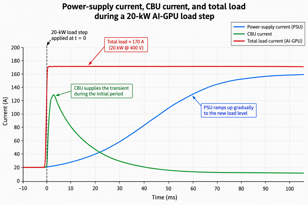
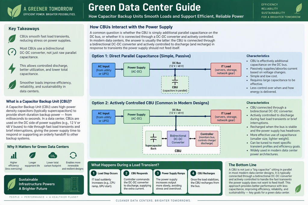
Figure 1. CBU Interaction with Data Center Power Supplies
- Direct-parallel capacitance architecture
- Actively controlled DC-DC converter architecture
- Load transient response sequence
Modern AI and high-density data centers experience dynamic electrical loads that are larger with greater swings than before. GPU clusters, AI training workloads, and high-performance compute systems can demand large bursts of power in milliseconds. These rapid changes create stress on power supplies, UPS systems, switchgear, and upstream electrical infrastructure (utilities).
One solution is the Capacitor Backup Unit (CBU), typically built around high power density supercapacitors. CBUs are used to provide short duration energy support, smooth load transients, and improve overall power-system stability.
The Fundamental Question
A common engineering question is:
Is the CBU simply additional capacitance connected in parallel with the DC bus, or is it an actively controlled energy storage system connected through power electronics?
The answer depends on the architecture, but in most modern data center deployments:
A CBU is usually not just a large capacitor bank connected directly to the DC bus. Instead, it is typically connected through a bidirectional DC-DC converter and actively controlled.
The distinction is important because it determines how effectively the system can manage power transients, improve efficiency, and reduce stress on the power supply.
Architecture 1: Direct Parallel Capacitance
The simplest possible implementation places capacitors directly across the DC bus.
When a load suddenly increases:
- Bus voltage begins to dip.
- Capacitors automatically discharge.
- Stored energy supports the load.
- Voltage droop is reduced.
When the load decreases:
- Bus voltage rises.
- Capacitors absorb excess energy.
- Voltage overshoot is reduced.
Advantages
- Simple design
- No active controls
- High reliability
- Low component count
Limitations
The capacitor current is determined by bus voltage, capacitance value, and circuit impedance. Engineers have little control over when energy is delivered, how fast discharge occurs, or available state of charge. As a result, large capacitance values are often required to achieve transient support.
Architecture 2: Actively Controlled CBU
Most modern CBUs use:
- Supercapacitor bank
- Bidirectional DC-DC converter
- Monitoring and control electronics
- Communication with power supply systems
Operating Principle
The controller continuously monitors the bus voltage, current demand, rate of load change, and capacitor state of charge. When a rapid load increase occurs the load jumps suddenly, so the controller detects the transient, DC-DC converter commands discharge, and the supercapacitors inject supplemental current. This allows the power supply to ramp more gradually.
When the load decreases surplus energy exists, so the controller initiates recharge so the supercapacitors absorb energy. This keeps the bus voltage stable. This approach allows the power supply to operate in a controlled manner rather than trying to instantly follow millisecond load fluctuations.
How CBUs Interact with the Power Supply
The interaction can be viewed as a division of labor:
| Function | Power Supply | CBU |
| Steady-State Power | Primary source | Minimal contribution |
| Millisecond Transients | Limited response | Primary response |
| Voltage Regulation | Moderate | Fast support |
| Energy Storage | Very small | Significant |
| Fast Current Delivery | Limited | Excellent |
The power supply focuses on delivering average load demand. The CBU handles the rapid changes that occur faster than the power supply can economically or efficiently respond to.
Why Power Supplies Prefer This Approach
Switch-mode power supplies are designed for higher efficiency, stable operation, and longer component life. Forcing them to chase every high-frequency transient can create increased switching losses, higher thermal stress, and reduced reliability. By allowing the CBU to absorb transient events, the power supply can run closer to its optimum efficiency point and experience lower component stress, improving lifespan and having tighter regulation.
Typical AI Server Example
Consider an AI server rack powered from a 48-VDC distribution bus.
Normal Operation: Rack load = 50 kW; Power supply delivers 50 kW; CBU remains charged
GPU Training Starts: Load jumps to 70 kW for additional demand = 20 kW.
Instead of requiring the power supply to instantaneously supply the extra 20 kW, the CBU delivers most of the transient power. This keeps the bus voltage stable and allows the power supply to ramp output gradually. Once the transient ends the CBU recharges. From the perspective of the power supply, the load appears smoother and easier to manage.
Data center betterments:
Higher Efficiency – Smoother load demand allows power electronics to operate closer to peak efficiency.
Reduced Oversizing – Without transient support, power infrastructure is often oversized to accommodate peak power excursions. CBUs can reduce the severity of transient peaks, allowing more efficient system sizing.
Improved Reliability – Lower component stress means longer PSU life, reduced thermal cycling, and overall improved system uptime.
Better Renewable Integration – Data centers increasingly use solar, fuel cells, BTM, and other solutions. Stable DC bus conditions improve integration of these variable energy resources.
Common Misconception
Many engineers initially envision a CBU as simply “a giant capacitor sitting on the DC bus.” While this is technically possible, it is usually not how modern data center CBUs are implemented. Today’s systems generally consist of:
Supercapacitor Bank → Bidirectional DC-DC Converter → Intelligent Controller → DC Bus
This architecture allows precise control of charging, discharging, and transient response while requiring far less total capacitance.